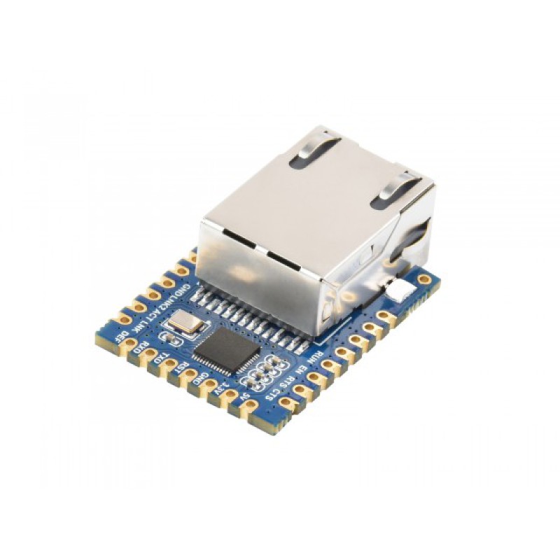
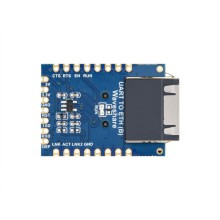
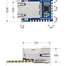
TTL UART to Ethernet Mini Module, Castellated Holes With Immersion Gold Design
It is a UART to Ethernet module designed for industrial environments, small in size, easy to embed and integrate, with device data collector/IoT gateway, serial server, Modbus gateway, MQTT gateway, UART to JSON, and many other functions in one. It has a UART interface and an Ethernet interface.

| Pin | Model | Description |
|---|---|---|
| 5V | Power | 5V Power Input |
| 3.3V | Power | 3.3V Power Input |
| GND | Ground | Ground |
| RST | Reset | Reset pin, low active. It is recommended to use max811reus or a similar reset chip. Noise can be filtered by a 0.1u capacitor. Low-level minimum time 100ns. |
| TXD | OUT | Serial data transmitting pin of the module, 3.3V TTL level, can be connected to RXD of user MCU. |
| RXD | IN | Serial data receiving pin of the module, 3.3V TTL level, can be connected to the user MCU's TXD. |
| DEF | IN | When the parameter is reset to 0 and held for more than 1 second, the module will restart with the default IP of 192.168.1.254, static IP mode, 255.255.255.0 gateway, and 192.168.1.1 gateway. You can also set your reset parameters with the param.txt configuration file. |
| RUN | OUT | Working indicator, the chip works properly, and will output a square wave with a period of 2 seconds. You can connect a 4.7K resistor and then connect the LED to the ground and the LED is on indicating the chip has been working. |
| EN | OUT | The 485 transmit controller, normally 0, becomes 1 when the module sends data to the serial port. It can be connected directly to the TXD_EN pin of the MAX485 chip. |
| RTS | OUT | Hardware flow control output. After the flow control is set to CTS/RTS, DTR/DSR, RTS=0 normally, if RTS=1, it means the module can't receive data and the user MCU should stop sending data to the module. |
| CTS | IN | Hardware flow control input, when the chip is configured for CTS/RTS, DSR/DTR serial mode, only when CTS=0, the chip serial port will output data to the outside. |
| GND | Ground | Ground |
| LINK2 | OUT | When it is 0, it indicates that the module RJ45 network cable is connected. |
| ACT | OUT | Data indicator. When it is 0, it indicates that data is sent and received at the serial port. But when there is data, this pin will jump between 0 and 1. ACT=1, which cannot be used as a flag for no data communication. |
| LINK | OUT | TCP connection indicator. When it is 0, the module has established the TCP/UDP connection with the network server, and the module can send and receive data normally. If the network cable is unplugged at this time, the LINK will change to 1. |

