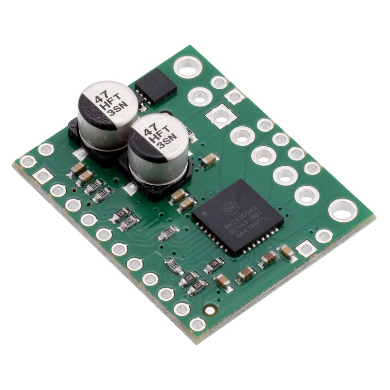
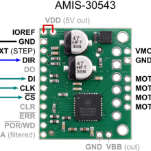
AMIS-30543 Stepper Motor Driver Carrier
This is a breakout board for ON Semiconductor’s AMIS-30543 microstepping bipolar stepper motor driver, which features SPI-adjustable current limiting, 11 step modes (from full-step through 1/128-step), back-EMF feedback that can be used for stall detection or optional closed-loop control, and over-current and over-temperature protection. The board operates from 6V to 30V and can deliver up to approximately 1.8A per phase without a heat sink or forced air flow (it is rated for 3A per coil with sufficient additional cooling).

This product is a carrier board or breakout board for ON Semiconductor’s AMIS-30543 Micro-Stepping Motor Driver; we therefore recommend careful reading of the AMIS-30543 datasheet (495k pdf) before using this product. This stepper motor driver lets you control one bipolar stepper motor at up to 3A output current per coil (see the Power Dissipation Considerations section below for more information). Here are some of the board’s key features:

- Standard step and direction control interface
- SPI interface for configuring settings (e.g. step mode, current limit, sleep) and reading status registers
- Speed and load angle output that can be used for stall detection or closed-loop control of the torque and speed based on the load angle
- Eleven different step modes: full-step (uncompensated, compensated 1-phase, or compensated 2-phase), half-step (uncompensated or compensated), 1/4-step, 1/8-step, 1/16-step, 1/32-step, 1/64-step, and 1/128-step
- SPI-programmable current control (from 132mA to 3A) enables your microcontroller to adjust the peak-current limit on the fly as more or less torque or speed is needed
- Intelligent chopping control that automatically selects the correct current decay mode (fast decay or slow decay)
- Low-EMI PWM with SPI-selectable voltage slopes
- Compatible with 5V and 3.3V microcontrollers
- Integrated 5V regulator that can be used to supply an external microcontroller
- Integrated watchdog function
- Open coil detection
- Thermal warning indicates when the driver is close to the thermal shutdown temperature
- Over-current status and shutdown (short-to-ground and shorted-load protection)
- Reverse voltage protection

Dimensions
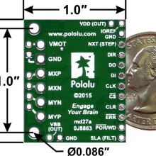
| Size: | 1.0″ × 1.2″ |
|---|---|
| Weight: | 4.0 g1 |
General specifications
| Minimum operating voltage: | 6 V2 |
|---|---|
| Maximum operating voltage: | 30 V |
| Continuous current per phase: | 1.8 A3 |
| Maximum current per phase: | 3 A4 |
| Minimum logic voltage: | 2.5 V |
| Maximum logic voltage: | 5.5 V |
| Microstep resolutions: | full, 1/2, 1/4, 1/8, 1/16, 1/32, 1/64, 1/128 |
| Reverse voltage protection?: | Y |
If you are new to the AMIS-30543 or stepper motors in general, our AMIS-30543 Arduino library can help you get started. The library provides basic functions for configuring and operating the driver using an Arduino or Arduino-compatible controller. It also provides access to many of the driver’s advanced features and includes example sketches that show you how to use them.
Power dissipation considerations
The AMIS-30543 driver IC has a maximum current rating of 3A per coil, but the actual current you can deliver depends on how well you can keep the IC cool. The carrier’s printed circuit board is designed to draw heat out of the IC, but to supply more than approximately 1.8A per coil continuously, a heat sink or other cooling method is required. However, it is possible to use the SPI-configurable current limit to selectively deliver higher currents than this for short durations without overheating the driver.

