5V Step-Up/Step-Down Voltage Regulator S13V30F5
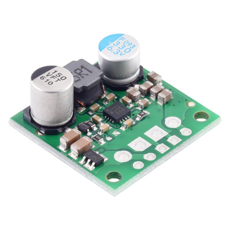
This powerful synchronous switching step-up/step-down regulator efficiently produces 5V from input voltages between 2.8V and 22V. Its ability to convert both higher and lower input voltages makes it useful for applications where the power supply voltage can vary greatly, as with batteries that start above but discharge below 5V. The board measures 0.9″×0.9″, has a typical efficiency of 85% to 95%, and can supply typical continuous output currents between 2A and 4A depending on the input voltage. The regulator also features reverse voltage protection and an optional enable input that can be used to put the regulator in a low-power state with a current draw of less than 10µA per volt on VIN.
The S13V30F5 switching regulator (also called a switched-mode power supply (SMPS) or DC-to-DC converter) uses a buck-boost topology to convert both higher and lower input voltages to a regulated 5V output. It takes input voltages from 2.8V to 22V and increases or decreases them as necessary, offering a typical efficiency of over 85% and a typical output current of 3A. The flexibility in input voltage is especially well-suited for battery-powered applications in which the battery voltage begins above 5V and drops below as the battery discharges. Without the typical restriction on the battery voltage staying above the required voltage throughout its life, new battery packs and form factors can be considered.
The regulator has input reverse voltage protection up to 20V, under-voltage lockout, output over-voltage protection, and over-current protection. A thermal shutdown feature also helps prevent damage from overheating and a soft-start feature limits the inrush current and gradually ramps the output voltage on startup.

Features
- Input voltage: 2.8V to 22V
- Output voltage: 5V with 3% accuracy
- Typical maximum continuous output current: 2A to 4A, depending on input voltage (see the maximum continuous output current graph below)
- Typical efficiency of 85% to 95%, depending on input voltage and load (see the efficiency graph below)
- 10mA to 20mA typical no-load quiescent current (see the quiescent current graph below); can be reduced to 2µA to 10µA per volt on VIN by disabling the board
- Input under-voltage lockout and output over-voltage protection
- Soft-start feature limits inrush current and gradually ramps output voltage
- Integrated reverse-voltage protection up to 20V, over-current protection, and over-temperature shutoff
- Fixed switching frequency of ~500kHz
- Compact size: 0.9″×0.9″×0.38″ (22.9mm × 22.9mm × 9.7mm); see the dimension diagram (294k pdf) for more information
- Two 0.086″ mounting holes for #2 or M2 screws
Dimensions
| Size: | 0.9″ × 0.9″ × 0.38″1 |
|---|---|
| Weight: | 3.5 g2 |
General specifications
| Minimum operating voltage: | 2.8 V |
|---|---|
| Maximum operating voltage: | 22 V |
| Continuous output current: | 3 A3 |
| Output voltage: | 5 V |
| Reverse voltage protection?: | Y4 |
| Maximum quiescent current: | 100 mA5 |
| Output type: | fixed 5V |


