


The TCA9548A / PCA9548A is an I2C multiplexer that allows up to 8 devices with the same I2C address to be hooked up to an MCU or permits up to 8 separate I2C buses to be controlled. The two modules are identical other than the TCA can operate down to 1.8V and the PCA can operate down to 2.3V.
KEY FEATURES OF I2C 8-CHANNEL MULTIPLEXER MODULE:
- 1 to 8 bi-directional I2C switches
- Allows level translation between individual buses
- I2C control interface
- 3.3 & 5V operation
One of the great things about I2C is that multiple devices can be hooked up to the same I2C bus if their addresses are unique. In some cases, a part may have a fixed address and therefore it is impossible to use more than one of the devices on the same bus or in another case, two different devices may happen to have the same fixed I2C address which also creates a bus conflict.
You may also want to separate a large number of devices on a single I2C bus into several smaller buses due to loading concerns or for bus isolation.
The TCA9548A addresses those issues by allowing a single master I2C bus to address up to 8 different slave I2C buses individually or in any combination. The multiplexer is given a command as to which bus(es) to use and then any future I2C communications will continue to use that bus configuration until commanded to use a different one.
The module uses the 24-pin TCA9548A or PCA9548A 8-channel I2C multiplexer chip. It supports I2C bus speeds up to 400kHz and allows level translation between 2.5V, 3.3V and 5V buses. The only difference between the TCA and PCA version is that the TCA can support down to 1.8V operation while the PCA can operate down to 2.3V. Otherwise they are identical and we don’t differentiate between them.
Master I2C Interface
The modules master default I2C address is 0x70. Address lines A0-A2 which are normally LOW allow the address to be set to the range of 0x70 – 0x77 by pulling the address pins HIGH. Pulling all 3 pins HIGH results in the address 0x77.
This allows up to 8 of these modules to be controlled by one I2C bus which results in the ability to control up to 64 slave buses.
The master I2C lines have 10K pull-up resistors included on the module.
Slave I2C Interfaces
The module has 8 slave I2C interfaces labeled SD0/SC0 thru SD7/SC7.
The slave I2C lines do not have pull-up resistors on the module. In most cases, the I2C devices being controlled will have pull-up resistors installed, but if not you should add a 4.7K to 10K pull-up resistor on the SDx and SCx lines that are being used.
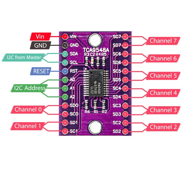
Module Connections
The board has two 12-pin male headers which give access to all the chip pins. All inputs are 5V tolerant. The header rows are on a fairly wide 0.7″ spacing.
1 x 12 Header (left)
- VIN = Supports 1.65V to 5.5V power (3.3 or 5V typical)
- GND = Ground. Should be common with MCU
- SDA = Master I2C Data
- SCL = Master I2C Clock
- RST = Reset active LOW. Pulled HIGH on module with 10K resistor by default
- A0 = Master I2C Address pin 0
- A1 = Master I2C Address pin 1
- A2 = Master I2C Address pin 2
- SD0 = Slave I2C Bus 0 – SDA
- SC0 = Slave I2C Bus 0 – SCL
- SD1 = Slave I2C Bus 1 – SDA
- SC1 = Slave I2C Bus 1 – SCL
1 x 12 Header (right)
- SC7 = Slave I2C Bus 7 – SDA
- SD7 = Slave I2C Bus 7 – SCL
- SC6 = Slave I2C Bus 6 – SDA
- SD6 = Slave I2C Bus 6 – SCL
- SC5 = Slave I2C Bus 5 – SDA
- SD5 = Slave I2C Bus 5 – SCL
- SC4 = Slave I2C Bus 4 – SDA
- SD4 = Slave I2C Bus 4 – SCL
- SC3 = Slave I2C Bus 3 – SDA
- SD3 = Slave I2C Bus 3 – SCL
- SC2 = Slave I2C Bus 2 – SDA
- SD2 = Slave I2C Bus 2 – SCL
Technical Specifications
| Operating Rating | Vcc | 2.3 – 5.5V (3.3 or 5V typ) |
| Clock Frequency | 0 – 400kHz | |
| Dimensions | L x W (PCB) | 31 x 21mm (1.2″ x 0.83″) |
| DIP row spacing | 17.8mm (0.7″) | |
| Country of Origin | China | |
| Datasheet | Texas Instruments | TCA9548A
|